RY Hifer Transmitter
What it Does:
"Hifer" is the cute name given to those who transmit in the 13.553 - 13.567 MHz
range under Part 15.225 of the FCC rules. Permissible power works out to be about
4.5 milliwatts into a ground-plane vertical. The RY transmitter was constructed
specifically for this frequency range.
Where is it?
RY is located in Raymond, Maine, at a summer cottage that is in our family.
The transmitter is located in the cellar, and the antenna is a vertical dipole
hung from a pine tree on the edge of the lake. Coverage from the south through
the west to the north has been excellent, as the lake lies in those directions.
Coverage to the east has been less due to the rising terrain and heavy tree cover.
I am limiting RY's operation to October through May, as the place is occupied
during the summer, and the antenna is needed for ham radio purposes.
History:
In the spring of 2001, when the 160-190 kHz "Lowfer" band became useless during the
thunderstorm season, several Lowfer operators began operating with slow-speed CW in the
13.555 MHz range. The idea was to give us something to do over the summer! I put a "TAG" beacon
on 13555.600 kHz from my Holden, MA address, on July 4, 2001, using a very lousy antenna. My first record of "RY" being
on the air is on July 16, 2001 from the Raymond, ME site. Operation at that point was intermittent, depending on
whether we were at the cottage. The frequency at that time was controlled by a 50 MHz clock oscillator, which was
quite temperature sensitive.
A couple of milestones were achieved that summer. The first was a rare Hifer 2-way QSO with MP on July 18, 2001. MP was
operated by Mitch Powell, VE3OT. We used hand-sent CW, slow enough to be readable on a QRSS3 screen. Signals were
audible much of the time, however, and I gave him a 559. Others may have had 2-way contacts around that time, but I haven't heard
anything about such activity since. The second notable event was a very weakly visible reception of RY by Steve, VK2ZTO in
Austrialia on August 14, 2001. I do not still have a copy of the screen shot -- some imagination was required,
if memory serves! I believe that Steve also copied Hifer LEK around that time.
Reception reports have been received mostly from the U.S. and Canada, though there have been a couple of
EU receptions over the years. Most of my activity has been just below or just above 13555.400 kHz, usually with QRSS3 or
DFCW3 (or 10), and not much normal-speed CW. Once the frequency was controlled by the OCXO module, there has been no trouble
leaving the transmitter on over the winter. During the summer, however, operation is intermittent. I believe that
RY has been on the air for part of each year since 2001. Access to the cottage can be difficult during the Maine
winters, and there were issues in at least one year that could not be fixed until spring.
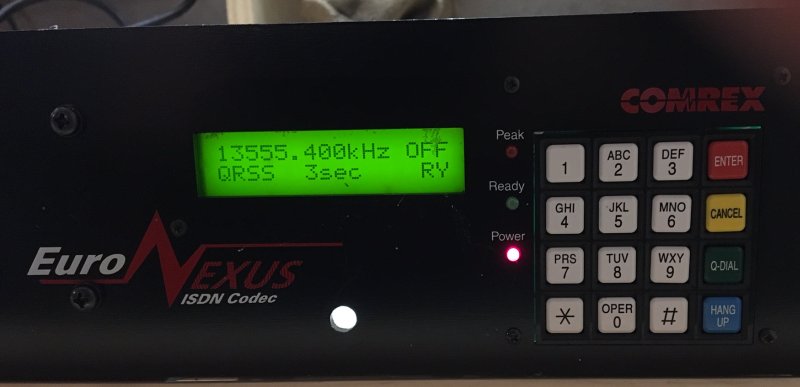
Equipment: The picture above shows part of the rack-mount front panel. The whole enclosure is a
re-purposed piece of equipment from Comrex Corp., my former employer. It
represents a handy use of a display and keypad -- nothing else was saved. The picture below is a view of the interior, with
the top cover removed.
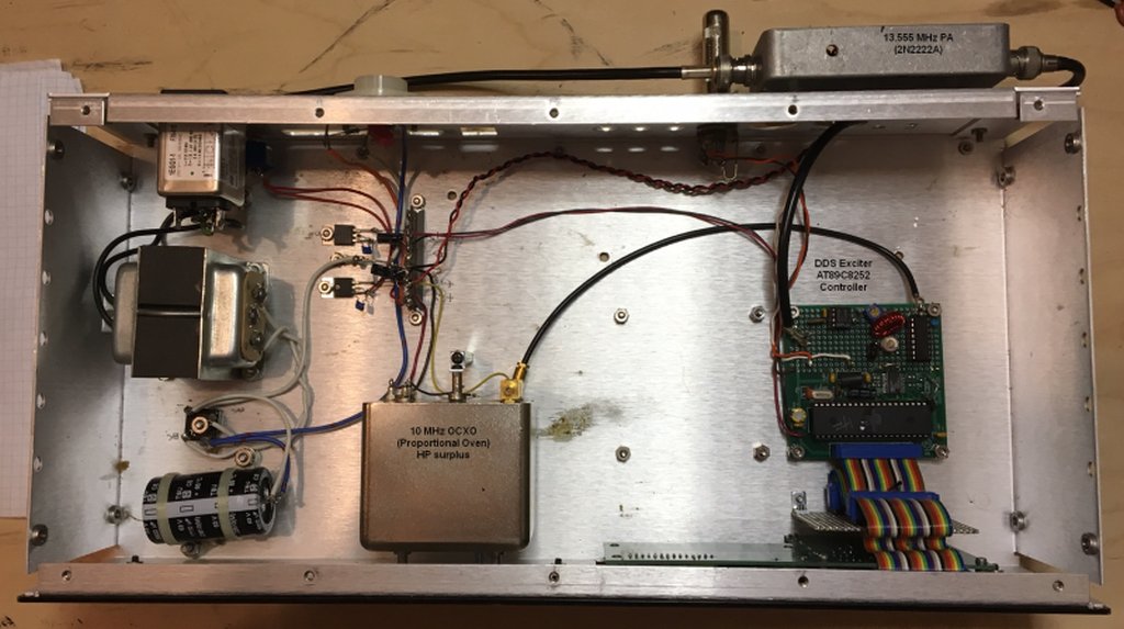
Frequency Control:
The exciter uses an Analog Devices AD9851 Direct Digital Synthesis (DDS) chip.
The chip is clocked by a 10 MHz Vectron OCXO obtained at a hamfest. The frequency
stability has been excellent for years, and easily withstands operation in an unheated
building during Maine winters.
Control:
The DDS chip is controlled by an Atmel 89S8252 microcontroller. Programming of
the controller is done in assembly language, and the printout is getting pretty
thick. A 12-button keypad and 2-line LCD screen are mounted on the front panel of
the exciter. They provide a menu system which allows selection of frequency, mode,
keying speed and ID. No computer is necessary to run the exciter/transmitter in
CW, QRSS, or DFCW modes. The frequency may be entered with the keypad down to
1 Hertz. The transmitter can be keyed manually through a jack
on the rear panel, if computer or "straight key" control is necessary.
Modes:
The basic exciter presently allows CW at 3, 6 and 12 wpm, QRSS at 3, 10, 30, 60
and 120 second dots, and DFCW at those QRSS speeds. As the DDS chip easily allows
0, 90, 180, and 270 degree phase shifts, many other possibilities exist if the
timing requirements can be met. Hifer operation is best done with dot lengths of
3 to 10 seconds, due to the rapid fading and propagation changes that occur at
this frequency.
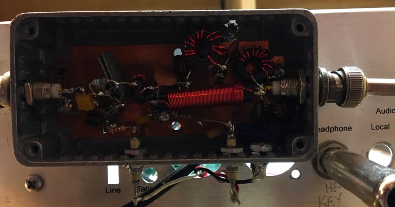
Output Stages:
The DDS output is fairly low-level. A bandpass filter follows the DDS chip, and
two buffer stages are used to drive the 2N2222A final located in the box on the
top of the case. Transmitter output is about +6 dBm into 50 ohms.
The antenna is a vertical dipole, cut for a half-wave at 20 meters, and fed with RG-58 coax.
The antenna is hung from a pine tree branch about 50 feet in the air. I found that a 75 pF capacitor
across the connector at the rig end would transform the impedance to about 50 Ohms. The transmitter
power output is set to compensate for the loss in the RG-58 coax run.
Back to Home


