137/472 kHz Transmitter - Revised November, 2017
Linear or switching? Most LF amateur/experimental transmitting is done with high-efficiency Class "D" or "E"
final amplifiers. Such amplifiers are straightforward to construct, and offer excellent power-line to RF output efficiency,
but they are not linear. For on/off keyed CW or FSK, this is not an issue, except for key-clicks. With the low data rates
typically in use, even clicks aren't much of a problem. But for BPSK, chirped HELL, and other modes generated by sound cards, linear
transmitters are significantly cleaner, and may be necessary to fit the signal in the regulatory bandwidth, as well as offer
some relief to other users of the band. Realizing that I was interested in operating with such modes, I considered building a
linear power amplifier. Then I started thinking about the circuitry in MOSFET-output audio amplifiers. Several of the U.K. guys
used such amplifiers on 73 kHz when they had that band, and the LF Experimenter's Handbook had some tips for keeping the
equipment happy.
An AUDIO amplifier? I don't think that Hafler intended such an application, but when I learned that they
rated the power bandwidth of some of their amplifiers at 300 kHz, I checked out a schematic for the P3000. After some head-scratching,
it was obvious that this was a good linear amplifier that would easily cover the 137 kHz range. I snagged one on eBay, figuring
that I would have to make some minor mods before it would be completely suitable. Not so! The Hafler P3000 was my main transmitter
as my LF from March, 2004 to September, 2006 without modification. Not convinced? A (750k) PDF file of the manual and schematic is
available here. In September, 2006, I acquired a used Hafler 9500 on eBay. Jay
Rusgrove, W1VD, had begun using a Hafler 9505 amplifier earlier that year, with excellent results. I have been running (unmodified) it at the 400
watt level since that time, and the P3000 has earned its keep as an AM modulator.
137 kHz Considerations: Tips in the LF Experimenter's Handbook suggested that you could not achieve full power
output from typical MOSFET-output power amplifiers, even at 73 Khz. Since Hafler had rated the P3000 to -3 dB (half power) at
300 kHz, I figured this wouldn't be a major limitation. The suggestion was made that the amplifier be terminated in a load
impedance greater than that used at audio frequencies. By using a 1:2 transformer, I could provide a 50/4 = 12.5 Ohm load,
which seemed to be reasonable for a nominal "8 Ohm" output. Later tests showed that this was correct. It also seemed a good
idea to reduce the output coupling at audio frequencies by using a series capacitor between the amplifier and
the transformer. An earlier choice of a capacitor to resonate inductance seen when looking through the transformer turned out to be
unnecessary after winding the transformer as described below. The three stacked FT-240-77 cores were necessary to prevent heating. I wrapped them
together with Scotch #27 fiberglass tape prior to winding. Choice of the core material for the filter inductors was not made lightly.
Early experiments with #3 material cores showed heating, and it was necessary to use cores requiring more turns. Calculations of flux density
on the large #2 cores predicted much less heating at full power, and the inductors have held up well.
Comments about output filtering indicated that an inductor-input low pass filter might provide more stability on an amplifier with negative
feedback than a filter with a shunt capacitor at its input. Finally, a 50 Ohm termination on the input would be a good idea,
along with an RF transformer to again limit the low frequency response.
2017 Note: Based on the work of Jay Rusgrove, W1VD, I have been using a 1:4 balun to replace the original output transformer.
See the description on his web site: http://www.w1vd.com/Haflertransformers.html.
A single transformer may be used for 137 and 475 kHz, with separate low pass filters switched by moving coaxial cables. W1VD and I have
used essentially the same filter design. So, for new work, I would suggest following Jay's approach to the Hafler output coupling.
Hafler 9500 Modifications: The schematic of the 9500 may be found here.
The first modification that I have made to the 9500 was changing the C13/C113 capacitors in the output
feedback loop from 680pF to 200pF. This was done to improve performance at 500 kHz without causing instability.
Playing with the 300pF cap at the input turned out to be a bad idea. Later investigations turned up a wrong part at C110, 22pF instead of 220pF.
I changed it to 220pF to match C10. That was probably an assembly error. The second modification was to add a 1500pF capacitor across R2, which
corrected a problem likely specific to my antenna system at 137 kHz. The resulting stability issue would be unlikely for any other user.
Hafler 9505 Notes: The Hafler 9505 is also an excellent candidate for this service. The trouble is that there are at least three
different production versions of this amplifier. The earlier two use through-hole parts, and the later one is mostly surface-mount. W1VD's Hafler 9505 is that
later model, with very different input circuitry. His results, particularly at 475 kHz, have definitely exceeded mine, and I would recommend the surface-mount 9505
over the older 95005's or my 9500 in this service. The performance differences at 137 kHz are not great, and any of these amplifiers should be fine
in that application. The problems at 475 kHz appear to be from phase differences between the two channels. When the outputs are summed in
bridging mode, the voltages and currents do not add as they do at lower frequencies. So, until the real source of the problem is discovered,
you should give preference to the surface-mount version of the Hafler 9505.
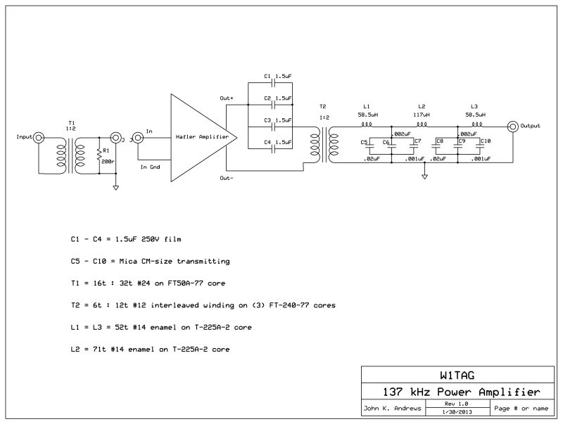
Results: The schematic above shows the setup in use on 137 kHz. It represents a number of changes since the P3000 first went on the air. The
output filter components and output transformer have been "beefed up" to reduce heating at high power. 500 watt operation
with the Hafler 9500 is entirely practical, assuming that cooling air is supplied to the heat sinks as described in the manual.
I am presently using two 4 3/4 inch AC-motor fans a few inches under the amplifier, each aimed at a heatsink. I also have
two 3 3/4 inch DC-motor fans on the top of the amplifier, centered on the vent holes, and blowing air up. With this arrangement,
the case runs cool at 500 watts continuous key down. I have not attempted to measure temperatures inside the case.
You may want to derate the power if the amp runs very hot with your cooling setup. But with any reasonable duty cycle, such as CW, full power is no problem. Note that the present
output transformer does not use windings on opposite sides of the core. Jay Rusgrove did some measurements on different winding styles,
and there is less leakage reactance if the windings are either interleaved, or simply wound over each other.
The input circuit was changed to a 1:2 step-up to raise the input level after I put a bandpass
filter between my DDS exciter and the Hafler amplifier. That filter reduces some spurs from the exciter, and should not
be necessary in most applications.
Testing: Jay Rusgrove, W1VD/WD2XNS, has done considerable testing on this setup, showing that the amplifier
is clean and linear at these power levels. Check out his report.
472 kHz Operation: The Hafler P300 amplifier has never worked well in this frequency range. I played with the feedback
networks, and only succeeded in creating instabilities. The 9500 amplifier has done pretty well, however, with the modification described
above. W1VD's 9505 appears to have greater output capability in this range - see his site for more information. My operation of the 9500
has been limited to 300 watts output. Above that, there is some risk of the amplifier going into oscillation when used with the antenna system.
If the amplifier is run into a dummy load, however, the instability does not occur. Also, a pole on the antenna relay connects the output shown
below to a dummy load while receiving. This prevents an occasional spontaneous "take-off" into an oscillation in the middle of the AM broadcast
band. Here is the schematic of the setup:
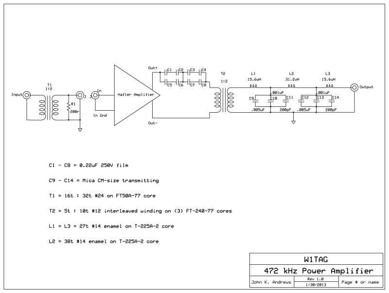
The output transformer, T2, could not be wound without producing some leakage reactance. The 77 core material is probably not ideal at these frequencies.
So I used the series coupling capacitor from the amplifier to tune out the residual reactance. In this case, 0.11uF was required, which I originally did
with two 0.22uF capacitors in series. After they burned up, I went to the present series-parallel arrangement shown in the diagram, and there have been
no further troubles.
Testing: Jay Rusgrove, W1VD/WD2XNS, has tested his Hafler 9505 in the 500 kHz range. He reports a maximum of 500 watts output.
Check out his report.
Back to Home