WD2XES Transmitting Antenna
History:
My QTH offers little open space for a loaded vertical antenna, as the back yard is narrow,
and bordered by trees at the edge of the lawn. The dielectric losses with such an antenna would be
significant, so I have stuck with loop antennas supported by trees. Loops at LF were not favorably
regarded until recent years. While they should not perform as well as a loaded vertical with a good
ground system in an open area, they are an excellent compromise for those of us with a lot of trees.
An excellent tutorial on transmit loops has been prepared by Bill Ashlock.
The first WD2XES antenna was a vertical rectangular loop, approximately 40 feet high and 65 feet long,
and put up with the aid of a slingshot. Despite being surrounded by trees, it performed quite well, and
the low data rate signal could be copied in Europe under good conditions.
Size:
The new loop was put up on December 5, 2004 with the aid of a bow and arrow. The goal was to have the upper
horizontal section of the loop be supported by the tops of the oak trees behind the house. As it was fairly windy
that day, several shots were required to achieve a reasonable length and orientation. The successful shot was made
with an arrow trailing 15 lb. test monofilament line. This was then used to pull a string over the trees, and the
string was used to pull a rope. The loop conductor is #4 gauge THHN stranded wire, purchased in a 500 foot roll. Pulling
the wire with the rope provided a LOT of exercise, as the rope was in several sections, and the knots kept snagging
on branches. The #4 wire also represents a lot of weight! We finally wound up with a horizontal length of 166 feet, and
since I had to cut only 15 feet of wire from the reel, the height of the antenna is on the order of 75 feet. As time has
passed, I have had a couple of arcing events, one to a screw holding a PVC standoff, and one directly to a small maple
tree. This suggests that the wire's insulation is important at high power levels. If I could find a cheap source of
RG-8 or RG-11 with good-quality braid, it would be a better choice than the heavy #4 electrical wire with thin THHN insulation.
Specifications:
The following will be revised as more measurements are made, but can be taken as pretty accurate:
Length = 166 feet (50.6 meters)
Height = 75 feet (22.9 meters)
Height of lower conductor above ground = 9 feet (3 meters)
Approximate orientation of maximum signal = 70/250 degrees true
Perimeter = 482 feet (147 meters)
Area = 12,450 square feet (1159 square meters)
Measured RF resistance (137.7 kHz) = 1.7 ohms
Calculated radiation resistance (137.7 kHz) = 1.87 milliohms
Calculated AC resistance of #4 wire (137.7 kHz) = 0.81 ohms
Calculated environmental loss based on above (137.7 kHz) = 0.89 ohms
Radiated power for 300 watts transmitter output = 330 milliwatts!
Turns ratio for coupling transformer = 16:3
WD2XES Antenna Tuning Unit
Description:
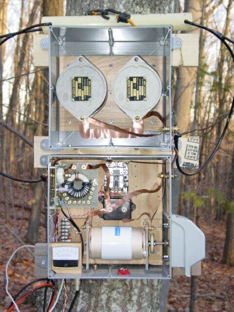
The tuning unit is built in two electrical cabinets purchased at Home Depot, and is mounted on a tree
which supports part of the upper antenna run.
The upper box holds two G3-size mica capacitors, a .01 uF and a .0075 uF, connected in series. Copper
straps connect the upper and lower boxes, and the remainder of the tuning capacitance is provided by a
40-4000 pF vacuum variable shown at the bottom of the lower box. The electrical box on the right side is
provided simply to weatherproof the tuning knob and bushing for the vacuum variable. The fixed capacitor in
the center of the lower box is now connected in series with the vacuum variable to reduce the voltage across the
VV at higher power. The loop connections are made to 1/4-20 studs on each side of the boxes.
As the diagram below shows, the loop circuit includes the capacitors, a 3-turn winding on the coupling transformer,
and a current pickup. The coupling transformer has taps from 14 to 21 turns. The loop circuit passes through
the current transformer toroid core on the left of the lower box. Removable shunts on that board allow a selection
of full-scale current ranges. The current transformer can also be isolated from the rectifier circuit and
used to inject or monitor current at low levels during impedance measurements. The relay in the top center
of the lower box is used to ground the antenna when not in use.
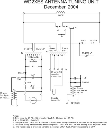
Schematic:
Impedance Measuring Setup
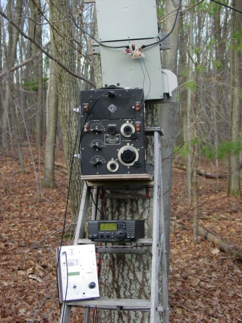
The above picture shows the setup to measure the impedance of the loop. The large black box is a General Radio 516C RF
impedance bridge, made in 1941. It connects through a series capacitor (800pF in this case) to the ends of the loop, which
have been disconnected from the gray tuning cabinet. Below the bridge, you can see the Icom R75 receiver used as a detector,
and the homebrew signal generator. All of this equipment must float above ground, so both the receiver and the generator are
battery-operated. Any attempt to use AC-power gear has provided odd measurements. The procedure to measure the impedance is to
hook up the equipment, short the connection to the loop, and get an initial balance of the bridge. Then the short is removed
and the bridge rebalanced for the antenna. The resistance is read directly from the three dials on the left side of the bridge,
and the reactance is calculated from the initial and final settings of the variable capacitor dial on the right side.
Back to Home