AC Line Filter for Switching Power Supply
I have an Alinco DM-330MV power supply that is used with an Elecraft KX3 transceiver and KXPA100 amplifier.
Unlike some supplies that have been used with other rigs, the Alinco supply is fairly clean of "birdies" at HF. It
also has a front-panel pot that shifts the switching frequency, allowing you to steer a spur away from a desired
channel.
But in listening with another receiver in the 137, 185 and 475 kHz ranges, loud spurious signals could be heard
when the Alinco supply was powered up. While the carriers could be shifted around with the pot on the supply,
there was an elevated noise floor, particularly at 137 kHz. Some detective work showed that that the spurs were being
coupled into the 120 VAC power line, and that the 13.8 VDC output was pretty clean. An AC line filter would have to handle
both common-mode and differential-mode signals, and given that the spur in the 137 kHz range was producing an S9 + 20 dB indication
on the external receiver, considerable attenuation would be necessary for weak-signal work.
A look at the interior of the supply showed little space for an additional decent AC line filter, so I decided to construct
an external filter using parts on hands. Such a filter would not be ideal for HF attenuation, but should be OK at LF.
The filter could fit into an existing 7" x 4.75" x 2" die-cast aluminum box. "Romex" connectors could be used at each
end of the box to bring out a short 3-wire power cord with a female connector for the Alinco supply, and a longer 3-wire
power cord with a male connector to connect to the AC mains.
Here is a schematic of the filter as constructed:
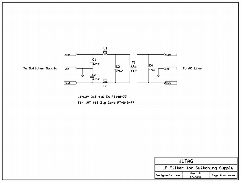
The filter "grew" from available parts, rather than by a proper design process. No computer power was used in the
development of this filter! The four capacitors were scrounged from commercial switching supplies. Note that they are rated
for operation on 240 VAC lines. C1 and C2 are 4.7nF each, ceramic Y2 capacitors rated for operation at 250 VAC. Y2 capacitors are
designed for connection from line to ground, and are impulse-tested to 5kV. The 4.7nF value (-j275 at 137 kHz) is pretty low for this application, but
it's what I had. I have an aversion to large line-to-ground capacitances, due to larger shock problems if something really goes wrong.
That said, 10nF would be a better choice in this application. Capacitors C3 and C4 are 0.47uF X2 film capacitors, again rated for
250VAC operation, and impulse tested to 2.5kV. Their -j2.5 Ohm reactance at 137 kHz is very nice. Use what you will, but for
safety's sake, be sure that the line-to-ground capacitors are clearly marked Y2, and the across-line caps are rated X2.
The inductors are wound on type 77 ferrite cores, excellent for use at LF. L1 and L2 should have the same inductance, in this
case 3.2mH (+j2760 at 137 kHz). I used #16 enameled wire because I had it. #18 would be fine, and would permit more turns. Insulation
on the wire is not critical, as you are only concerned with the small voltage between turns. I used one layer of Scotch 27 glass tape
over the L1 and L2 cores, which should prevent any breakdown to the core. The common-mode transformer, T1, is wound with 18 guage
"zip cord" directly on the ferrite core. I was able to fit 19turns on the 2.4" core, giving about 950uH for each winding (+j818 at 137 kHz).
The insulation on the zip cord is appropriate for 120 VAC operation.
Construction is not critical. VHF techniques are not required! Here's a shot of the completed unit:
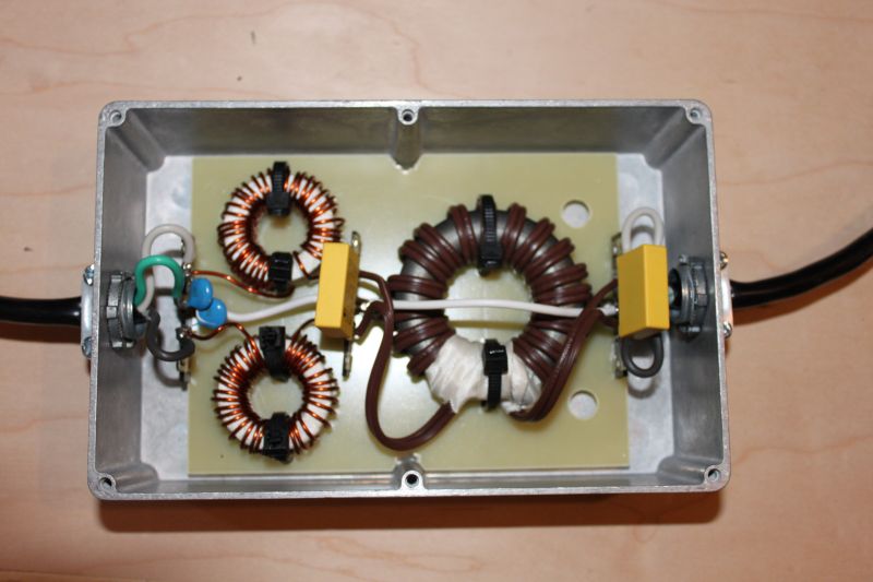
The filter is built on a piece of unclad PC board. Three 5-terminal tie strips are used for electrical connections. The ferrite
cores are secured to the board with tie-wraps through holes drilled on the board. The Romex connectors provide a good strain relief
for the AC cords. I simply used a 6 foot three-wire extension cord, with about 1 foot on the female side, and the rest on the male
side toward the power line. That's it!
Performance of the filter has been excellent. The tunable "birdie" in the 137 kHz range is now below audibility, and off the s-meter
scale. Monitoring of VE3OT's QRSS60 signal on 137.780 kHz during the daytime on another receiver, shows no difference whether or not
the Alinco supply is turned on. It's probable that the "birdie" itself would be visible on such a screen, but as it has poor stability, it
shouldn't show a persistent trace.
I hope this information is of some use, should others have a similar problem with LF reception.
Back to Home