RF Ammeters for LF Use
Thermocouple RF Ammeters are widely available from surplus outlets and flea markets.
Many models exist, but the Weston 308 and 425 meters were the most common in AM broadcasting. Be sure that
the meter you buy is self-contained; some meters with "RF Amperes" scales are just DC milliameters that were
used with external thermocouples.
When purchasing a used meter, note whether the scale is appropriate to the current range you expect to use.
In general, thermoucouple meters are non-linear, and the low end of the scale can be compressed. A 20 Amp
full-scale meter won't be much use in a 2 Amp circuit. Be sure not to mount thermocouple RF ammeters on a
metal panel, as the calibration will be affected. Quarter-inch acrylic plastic material is good for panels.
Note that thermocouple-type RF ammeters are temperature sensitive; they tend to read higher in cold weather.
The Weston 425 models had some temperature compensation, but you will still notice a difference.
Any used meter should be checked for calibration. Almost all self-contained RF ammeters can be tested at 60
Hz. If you have a decent digital multimeter that reads AC Amperes, it can be placed in series with the RF
ammeter in a 60 Hz circuit, and the readings compared. Best results will be from a true-RMS digital meter, as
the waveform will be less of an issue. A handy source of high current can be generated by a hefty filament
transformer fed from a "Variac" or other autotransformer. Just put the meters in series right across the filament
side of the transformer. Crank up the "Variac" and compare the readings. If the calibration is not exact,
you can translate the error into a percentage, and just remember that your RF ammeter reads 5% low, or whatever.
Thermocouple-type RF ammeters are appropriate for Lowfer, Experimental and Amateur vertical ("Marconi") antennas,
as the resistance of the thermocouple and its shunt is low compared to the antenna resistance. Very little power
will be lost due to the insertion of the meter, and in fact it may be left in the circuit permanently. If lightning
is expected to be an issue, you might want to put a knife-type shorting switch across the meter, using short,
low inductance leads.
Current Transformer RF ammeters can be built inexpensively, and are the weapon of choice for
measuring current in low resistance circuits such as LF transmitting loop antennas. They are commercially available,
and the independently wealthy may want to check out Delta Electronics' Site
for a look at how the pros make these things.
Current transformers in this application are usually ferrite toroid cores with a one or two turn primary and
a number of turns on the secondary and a resistive termination. Just bringing the antenna lead through the
core results in a one-turn primary. If you loop it around the core once, you will have two turns.
The voltage across the terminating resistor is measured with a simple half-wave rectifier and filter. Since
this responds to the peak value of the voltage, it is necessary that the antenna current be a sine wave. This is
almost always true in LF installations, due to the high "Q" of the antenna circuit. Do keep it in mind as a limitation
for bench-top work, however.
A simple current transformer circuit can be drawn like this:
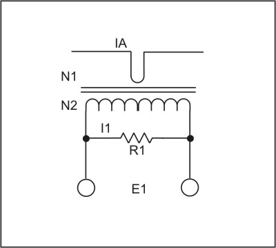
The current through R1 will be I1 = IA (N1/N2). For example, if the antenna current, IA, is 1 Ampere, and
the turns ratio is 1:50, then 20 mA will flow through R1. Within reason, that 20 mA will exist over a wide
range of values for R1.
The choice of R1 and the turns ratio is a balancing act. You want to have enough RF voltage, E1, to drive a rectifier and meter
circuit over a reasonable range. On the other hand, you don't want to reflect too much resistance back into the primary circuit and
add loss to your nice low-resistance antenna. The amount of resistance reflected back will be R1 ((N1/N2)^2) ohms. Let's say that you
are using the 1:50 turns ratio mentioned above. If R1 were 50 ohms, then E1 = 1 V(RMS), and the reflected resistance is 20 milliohms.
If the antenna resistance was 1 ohm, then that would be an increase of 2%, which might be considered OK. But that 1 Volt RMS across R1
might not be enough for a decent linear range from a half-wave rectifier with a germanium diode.
A practical example should help you get started. Let's say that you have a very nice LF transmit loop antenna with an RF resistance of 0.5 ohm.
Assuming a 100% efficient one-watt transmitter, the antenna current would be 1.414 Amperes. So you decide to build a 0-2 Amp RF ammeter, and just
happen to have a 200 microamp DC meter lying around. Now you know that a 1N34A germanium diode is going to be non-linear with less than 0.5 VDC
across it, so you plan on feeding your half-wave rectifier with 5 Volts peak with the full 2 Amps of antenna current.
The filter capacitor following the diode will charge to 5 Volts less about 0.5 Volts for the drop across the 1N34A. If the peak voltage across R1 is
5 Volts, then the RMS value must be 5 (0.707) = 3.54 Volts. Now think about your nice
0.5 ohm antenna resistance. Let's say that you are willing to increase that by no more than 4%. That would be 20 milliohms. A turns ratio of 1:100
would put 2 (1/100) = 20 milliamps into R1. Since we want 3.54 VRMS across that resistor, it must be 177 ohms. A check on the reflected resistance
shows 177 ((1/100)^2) = 17.7 milliohms, which meets our goal. If you want a lower reflected resistance, be ready to wind a lot of turns, or lower your
expectation for voltage across R1.
Now we can put together the rest of the schematic:
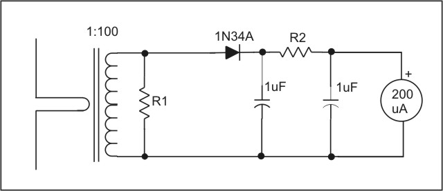
Having chosen 177 ohms for R1, make up an accurate non-inductive resistor of at least 1/4 watt power rating. The value for R2 may be determined by
breaking the connection between R1 and the 1N34A, and feeding an accurate 5 VDC into the diode. You can temporarily use a pot for R2, and adjust it
for a full 200uA reading on the meter. This will correspond to 2A of RF current. Measure the pot, and install the appropriate fixed resistor. If you
wish to calculate the value for R2, you will need to know the internal resistance of the 200uA meter. As an example, let's say that it is 500 ohms.
With a 0.5 volt drop across the 1N34A, R2 = ((5 - 0.5)/0.0002) - 500 = 22,000 ohms.
The remaining issue is about the choice of a toroid core. I strongly suggest ferrite rather than powdered iron, as you want the inductive reactance
of the secondary to be at least 5 times (and preferably more) greater than R1. #43 material should be OK, though I have pretty much stuck with #77 at
LF. The size of the core has more to do with the number of secondary turns and possible arcing from the primary than any consideration about core heating.
The magnetic flux level in the core will not be very high, and heat will not be an issue. But remember that you may have kilovolts on the antenna
lead, and you don't want that arcing to the secondary winding should something get grounded. While the 100 turns (or whatever you use) on the
secondary can be wound in multiple layers, it may make sense to use a fairly large core for ease in winding. I typically wrap a ferrite core with Scotch
27 fiberglass tape, and then use enamelled wire. Wire size is not at all critical, and 24 - 28 gauge should be fine.
If you want a remote-reading ammeter, I strongly suggest not grounding anything on the secondary side. It might be nice to use a twisted-pair cable
back to the shack -- something like Cat 5 cable would be good. You could run it through a common-mode RF choke made from a single pair of Cat 5
wire wound on a ferrite core. That would add some isolation from the secondary circuit.
The resulting meter should be fairly accurate over the upper 3/4's of it's scale, using the original meter markings. You could do a more accurate
scale at the low end by feeding known DC voltages as described above, and marking the meter accordingly. If different meter ranges are required,
you could use banana jacks for R1, and install different terminations as required. I have options for 5, 10, 15 and 20 amps full scale on the WD2XES
ammeter.
The commercial meters mentioned earlier have temperature compensation, and Faraday shields around the center conductor. My feeling is that the e-field
screening is not terribly important at LF, so I haven't done it. The temperature compensation is very useful in broadcasting applications, making the
meter much more stable than even the best thermocouple meters, but is probably not all that important for casual experimental work.
Note on December 15, 2006: I did a calibration check on the meter described above. I presently have a total of 25 ohms resistance in shunt on the
current transformer, giving a full scale reading of 20 Amperes. I inserted a professionally-calibrated 0-20A Weston 425 meter in series with
the antenna. When my meter read (40uA/50uA)*20A = 16.0 Amperes, the Weston meter read 16.0 Amperes. Pretty good!
Back to Home