Low Frequency Phasing Exciter
As of this writing, two programs are available for data transmission at low frequencies that use a computer sound card
and output the audio in an I/Q format. JASON has a unique FSK format with a variety
of data rates. The "DigiMode Terminal" in Spectrum Laboratory generates PSK and MSK signals
suitable for LF work. If you are new to all of this, check out the Low Frequency Transmission Mode
article on this site.
The problem is that most LF Amateur or experimental operators use on/off keyed transmitters. The SSB rigs that are common in Amateur HF
work are rare at LF, mostly due to the lack of commercial products and the complexity of building one's own. SSB generation by the phasing
method avoids the need for expensive crystal filters, but the need for both RF and audio frequency phasing networks can dampen your
enthusiasm. By providing quadrature I/Q sound card outputs, the above programs allow a simpler exciter design. In both cases, the tones
on the "right" channel output lag the "left" channel by 90 degrees. This removes the need for a separate audio phasing network, and the exciter
needs only to provide the RF phasing and the modulators. Some of the modes in these programs require that the remainder of the transmitter
be linear; others do not, and you are advised to check that out in advance! Credit should be given to Phil Rice, VK3BHR, for his article,
"SSB by the Fourth Method. I would disagree that use of a commutating
mixer constitutes another method of SSB generation, but his circuitry is certainly very useful.
This project uses easily available components to provide a very clean translation of the audio tones up to the 135.7 - 137.8 kHz or 160-190 kHz
LF bands. Few adjustments are required, and no special test equipment is needed. You will have to provide a local oscillator at four times
the carrier frequency. This approach removes the need for a "tweakable" RF phasing network. The stability of the oscillator will have to be
quite good if you are to take advantage of the slower data rates. A DDS or other synthesized exciter would be good, as would the tracking
output of a selective level meter like the HP 3586 series. But a simple HF crystal oscillator with dividers down to the 4X frequency should
suffice if you can maintain temperature stability. Use of a PTC thermistor for crystal heating is discussed in the "All in One Transmitter" article
at Lyle Kohler's Site. A 1 volt peak to peak signal should be sufficient to drive the
phasing exciter.
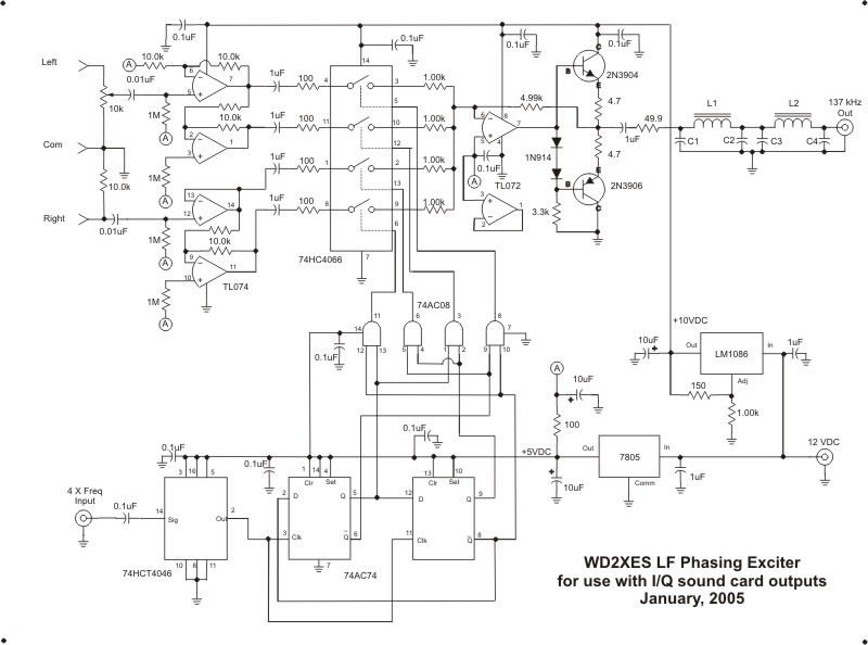
Schematic
Circuit Discussion
The RF Input at four times the carrier frequency is run through a 74HC4046 for conditioning. The PLL features of the chip are disabled,
but the circuit shown will nicely condition a wide variety of input voltages and waveforms. If you have a favorite analog to TTL level converter
circuit, feel free to substitute it. The 74AC74 is wired as a Johnson Counter, providing a four-phase output. Ideal drive for the 74HCT4066
commutating mixer is four clock lines, each of which is high for 1/4 of a cycle. The 74AC08 gates decode the Q and /Q signals from the counter,
providing a glitch-free count. For troubleshooting purposes, the output sequence of the AC08 is pins 8, 11, 3 and 6.
The audio input is taken from the left (I) and right (Q) outputs of a sound card. I have been using 800 Hz, and there is no need to
run at a higher frequency as the sound card output is quite clean. A 20-turn trimpot is provided for accurate amplitude balance, which sets the opposite
sideband rejection (LSB in this case). The typical
Windows mixer slider operation is too coarse to provide a fine adjustment. If the software you are running allows an amplitude tweak, you can
eliminate the pot and convert the top section of the TL074 to unity gain. The four sections of the TL074 provide buffered and inverted versions of
the I/Q inputs. The op-amps are biased to half the supply voltage by a decoupled output (A) from the 5 volt regulator. Coupling capacitors
are used between the op-amps and the 74HC4066 switches to eliminate the need to balance the DC offsets of the four sections. The 100 ohm resistors
are left from an earlier version of the exciter, and may not be necessary. I have, however, experienced unstable operation of unity gain buffers
when directly connected to a switch in other projects.
The mixer uses four switches which are engaged in an I, /Q, /I, Q sequence to produce an upper sideband. If you wish to use the lower
sideband, just swap the left and right inputs to the exciter. The carrier null has
no adjustments, and remains at about 60 dB with or without audio. The outputs of the switches are summed through 1% resistors into the inverting
input of the TL072.
The RF amplifier uses a TL072, not a spectacular choice for this application, but it works. The 072 will not drive a low impedance
load, however, so the 2N3904/3906 pair is used as a Class-B output. A 49.9 ohm resistor gives a proper termination to the half-wave output filter,
and protects the output stage. I used an LM6181 current-feedback opamp without the transistors in an earlier version, and it worked well. The LC values
for the filter are the only frequency-sensitive elements in the exciter, and are:
| Frequency (kHz) |
L1, L2 |
C1, C2, C3, C4 |
| 135-138 |
55 uH (55T #24 on T-80-3) |
0.022 uF |
| 180-190 |
38 uH (46T #24 on T-80-3) |
0.015 uF |
The power supply takes a 12 volt nominal input. I used an LM1086 low-dropout regulator to provide 10 volts. Operation should
be fine with an input voltage as low as 11. If you can insure a 13 volt or greater source, then you can use the more commonly available LM317.
The resistor and capacitor values will be the same. A 7805 regulator provides 5 volts for the logic circuitry and as a reference for the opamps.
Construction
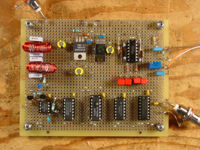
Construction of the prototype was done on perfboard. At these frequencies, just about anything will work!
Setup
Connect an 11-18 volt power supply that will provide 150 mA. Audio connections should be made with shielded cable, and an external
L.O. signal should go through coax. If a high power transmitter is involved, take care that stray RF is not coming in through the audio and L.O. cables.
If the actual on-air carrier and LSB suppression do not live up to expectations, that would be a sign of an unwanted RF path. Possible cures include
better shielding on the audio cable and winding part of the external cables onto high-permeability toroid cores. While the RF output is designed to be
terminated in 50 ohms, it will work OK into a higher impedance.
If you have an oscilloscope, set the sound card output for 1 volt peak to peak while running the desired program. Be sure that the balance slider
on the Windows mixer is centered. You can use the scope to verify that audio is present on all four inputs to the 74HC4066 mixer, and that 1/4 cycle
pulses are being fed to the mixer switch ports. The only hardware adjustment is to set the LSB null. You can use your receiver to do this, but be
sure that no stray signal is getting around the exciter. The best approach is to couple the exciter directly to the receiver through a high-attenuation
50 ohm pad -- I would suggest 40 dB or more. Be sure that the receiver is not being overloaded, and tune to the carrier frequency minus the frequency
of the audio tone. You should be able to get a very sharp null by adjusting the 10k trimpot in the audio section. If the program you are running
offers a "tweak" of the amplitude and phase, you can play with those on-screen adjustments to get a better null.
At this point, you should have a very clean sine wave of about 2 volts peak to peak into 50 ohms at the exciter output. A check
with your receiver should show very little signal at the carrier frequency, and a strong signal at the desired USB. If not, it's time to check
your wiring. A dual trace oscilloscope will allow you to verify the phasing of the audio and RF signals.
Specs
Carrier Suppression: 60 dB below the USB.
LSB Suppression: >60 dB below the USB if the audio phase can be tweaked with the program.
Harmonics: >50 dB below the USB.
Other Spurs: >50 dB below the USB (one exception, see To Do List).
Output Level: +10 dBm (50 ohms) for 1 volt p-p audio input.
L.O. Drive Level: Requires 1 volt p-p or greater.
To Do List
There is a pesky 3rd level lower sideband (carrier frequency - 3 X audio frequency) that is only 45 dB below the USB. It appears to be the only
significant distortion product. At 1 kilowatt, that would only be 32 milliwatts, but its presence is still irritating.
If there is enough interest in a circuit board, I might have a way to get it done. Otherwise, perfboard or dead-bug construction is fine.
Back to Home