1
Loop Antennas for 630 Meter Transmitting

Background:
The conventional transmitting antenna for the low MF range is a vertical conductor, possibly top-loaded,
working against a ground wire system. For amateur "back-yard" use, such antennas have the disadvantage that
their near-fields are principally electric fields, and dielectric losses in nearby trees, shrubbery, houses, etc.,
can be high. In New England, we are favored with many trees and lousy ground conductivity, and as a result, performance
of back-yard "Marconi" style antennas is frequently poor. This article presents a practical example of the use of a
vertical loop antenna supported by trees in a heavily wooded area. Such antennas have dominant magnetic fields near
them, and the trees are less of an issue as a result.
The "Camp Loop":
The traditional definition of a small loop antenna is one with a perimeter of less than 0.1 wavelengths. For MF use,
the loop would need to be vertically polarized, and it's classic figure-8 pattern would be strongest in the plane of the
loop. Here is some info on a loop used at my site in Maine -- it was put up some years ago for other purposes.
The loop is roughly square, supported by pine trees in several spots.
The plane of the loop is on a 50/230 degree (true) bearing.
Dimensions: 63' x 63' (19.2m x 19.2m).
Perimeter = 252' (76.8m) => 0.122 wavelength.
Area = 3969 square feet (368.7 square meters).
Conductor = Very old RG-8 with tinned braid, shield is 0.27" diameter (6.9mm).
Lower conductor run is 8' (2.4m) above ground.
The feedpoint is off-center in the lower run. Feedpoint impedance measures 3.65 +j366 ohms at 475 kHz.
Expectations:
The choice of RG-8 as a conductor, rather than a solid or stranded wire, is based on skin-effect, where the
interior of the conductor is relatively unimportant, and the expense and weight of copper is not justified. In
this application, the braid and center conductor are connected together at each end.
Impedance measurements of loop antennas are complicated by the need to have the test equipment isolated from
ground. As the feedpoint and tuning network are at a tree, I put a temporary wooden shelf on the tree, and put
my VNA2180 analyzer and a laptop computer on the shelf. Battery power was used for both.
An analysis of the above information in the old but excellent program "RJELOOP"
http://www.zerobeat.net/G4FGQ/page3.html gives the following:
Inductance = 120.6uH.
Radiation Resistance = 0.0266 ohms.
Conductor RF Resistance = 0.639 ohms.
The program also gives a ground loss resistance, but since we have an actual feedpoint measurement, we are better off
doing the math ourselves, since RJELOOP does not do a good job with our sandy, rocky New England soil. The actual
ground (or environmental) loss would be: 3.65 - 0.0266 - 0.639 = 2.98 ohms. But the most important figure would be
the expected efficiency, which would be (0.0266 / 3.65) = 0.73%. Thus for my 150 watt transmitter, the radiated power
would be (150 * 0.0073) = 1.09 watts. Because a theoretical half-wave dipole in free space and a loop in free space
produce the same far-field radiation, this 1.09 watt radiated power can be called ERP under FCC terminology. To determine
EIRP, multiply by 1.28 and get 1.4 watts.
Antenna Tuner:
The measured 3.65 +j366 feedpoint impedance needs to be transformed to 50 ohms for connection to the coaxial feedline
to the shack. Also, it would be useful to have a fairly accurate indication of current in the loop. The tuning and measuring
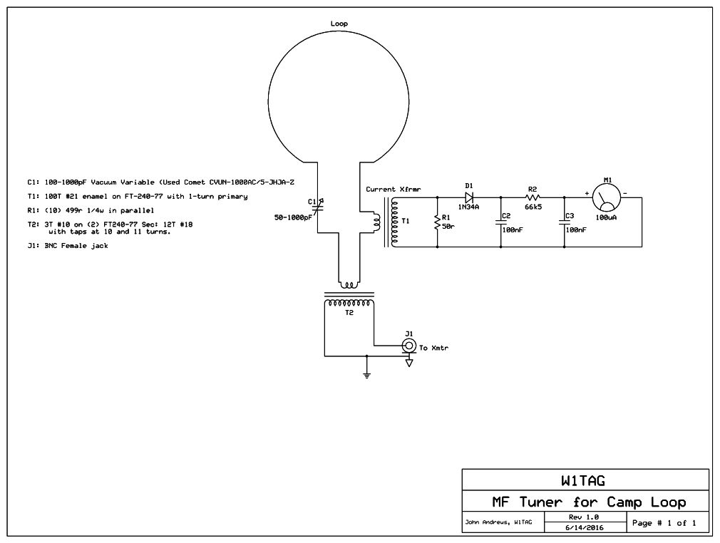
components need to be contained in a weatherproof cabinet at the feedpoint. Here is
a schematic of the tuning unit. C1 tunes out the reactance of the
loop in series with any leakage reactance from the coupling transformer, T2. At 475 kHz, the required capacitance for the
loop inductance is 915pF. While a 1000pF variable capacitor is a bit borderline, it works. At the time that I needed the cap,
nothing was economically available in the 1500 to 2000pF range. There are a couple of considerations about this capacitor. It
must carry the loop current, which is 6.41A for 150 watts. It also has considerable voltage across it: 6.41 x 366 = 2.35kV RMS.
This rules out anything but a physically very large air variable. A vacuum variable is a much better choice, and I found a
relatively small 100-1000pF Comet unit on eBay.
Coupling transformer T2 is pretty simple. A turns ratio of SQR( 50 / 3.65 ) = 3.7:1 is needed to get to 50 ohms. A transfomer with
a 11:3 ratio is perfect. I used two FT-240-77 cores, taped together with Scotch 27 glass tape. The antenna side is 3 turns of
#10 electrical wire, and the line side has 12 turns of #18 wire with taps at 10 and 11 turns. As expected, the desired tap was
at 11 turns.
T1 is a current transformer with the loop conductor passing once through the center, for a single turn. The FT-240-77 core is
wrapped with Scotch 27 tape, and then wound with 100 turns of #21 enamel wire. Another layer of tape goes over the winding. When
terminated with a 50 ohm resistor, 1/100 of the antenna current will pass through the resistor. For 10A full-scale, 5V RMS will
appear across the resistor. That is rectified by D1 (should be germanium), and filtered by C2. This should give a full-scale
voltage of 7.07 - 0.3 = 6.77V DC across C2. R2 is then used with a 100uA meter for a full-scale reading. Calibration may be
done by disconnecting T1, and applying 7.07VDC across R1.
Tuning Unit Construction:
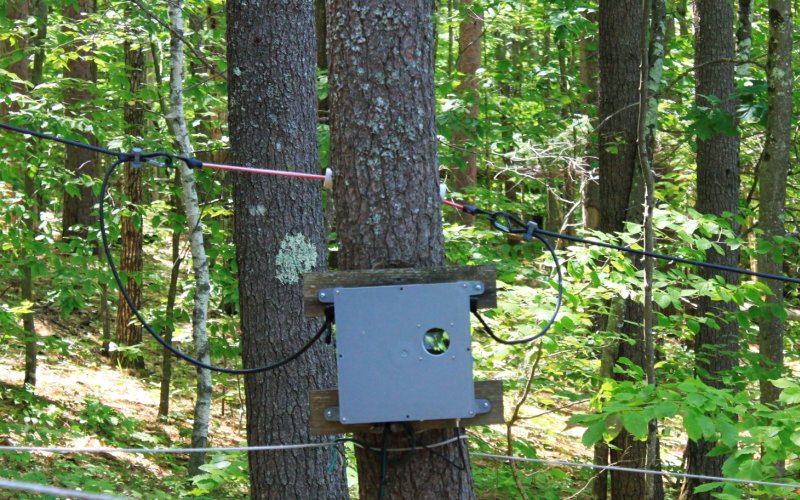
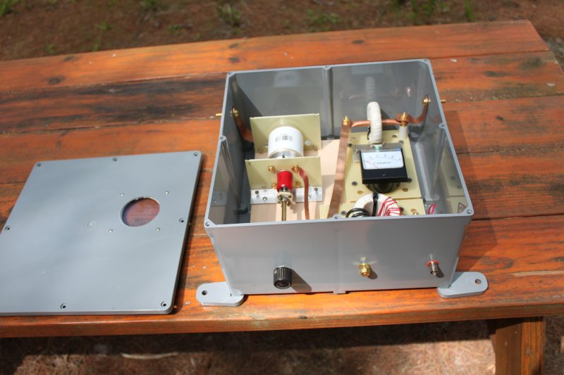
The tuning unit was built in a 12" x 12" x 7" plastic outdoor electrical cabinet available from Home Depot. This box can
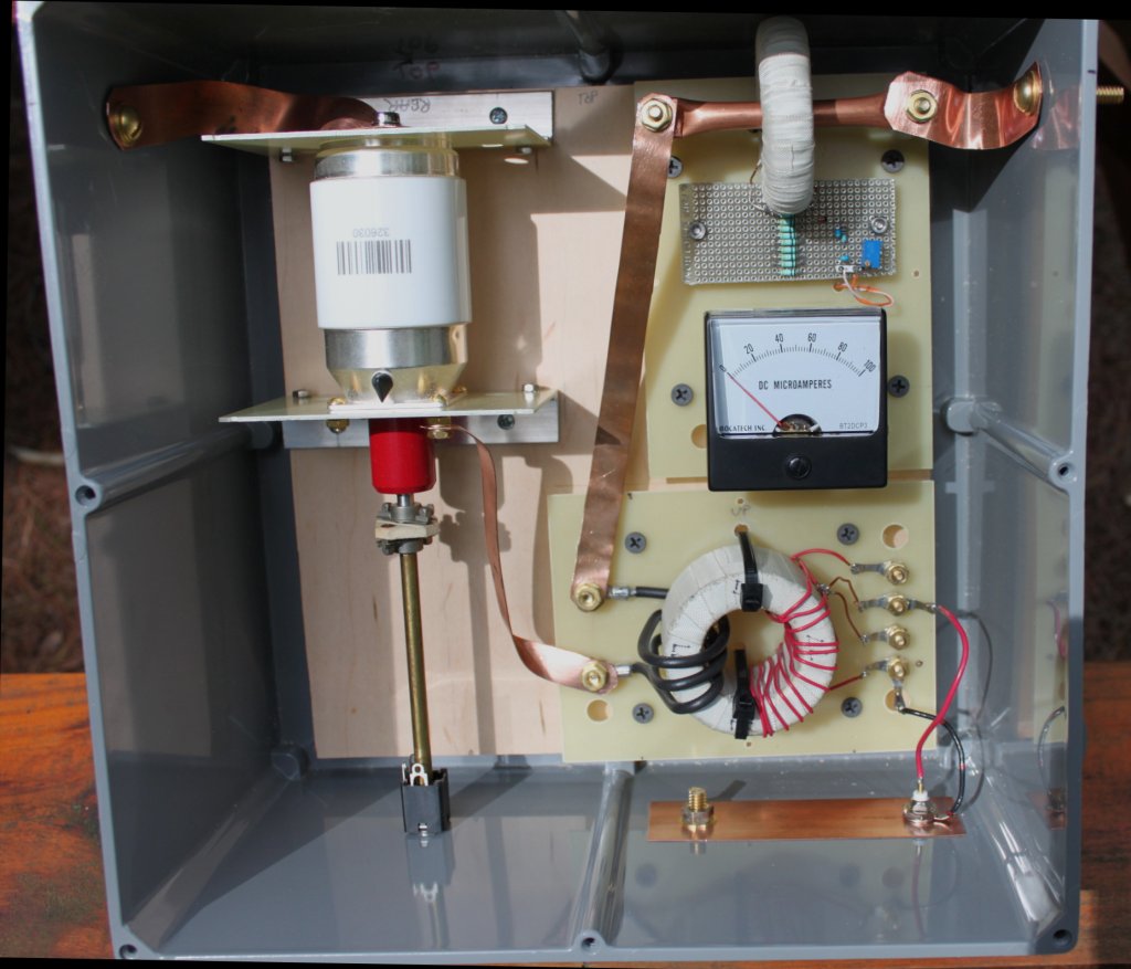
easily be mounted to the tree at the feedpoint. A view of the
interior of the box shows the plywood backboard onto which
the various components are attached with wood screws. Connections to the loop are made with 1/4-20 brass bolts. Interior
connections are done with copper strap or tubing. Note the copper tubing running through the center of T1, forming the
single-turn primary. The vacuum variable capacitor is mounted with two pieces of unclad glass-epoxy circuit board attached
to aluminum angle stock and screwed to the backboard. Note the insulated coupling on the shaft of that capacitor. The brass
shaft will be replaced with something non-conductive, as it is still possible to "get bit" if you touch the setscrew on the
knob at the end of the present brass shaft. A 1/4" phone jack is used as a bushing for the tuning shaft...cheap, but it works.
The unclad boards with the output transformer and antenna ammeter are mounted with wood screws running through nylon spacers
behind the boards. I suggest sticking with brass hardware as much as possible. Stainless steel can be quite lossy at
radio frequencies. A view of the bottom of the box shows
the tuning knob, ground stud (presently unused) and BNC output connector. Note the window in the box cover to allow
viewing of the ammeter.
Tuneup:
My 150 watt Class D transmitter is happiest when the vacuum variable is simply tuned for maximum antenna current. I do have
an SWR bridge in the shack, and presently note that maximum output (and best efficiency) do not necessarily coincide with minimum
SWR at the transmitter end of the feedline.
Loop Thoughts:
A transmit loop antenna has a couple of shortcomings. First, there is a lot of high-angle radiation, which contributes to fading
in reception in "regional" coverage. Second, the fat figure-8 horizontal pattern means sharp nulls at right angles to the
antenna. Choose your trees accordingly. While doing that, consider trying to minimize the lower part of the loop closest to
the ground. An ideal shape would be circular, perhaps by shooting a line over a tall tree with a large canopy (pines need not
apply). Ground loss would be less than with a square or rectangular loop having a long lower conductor. Feel free to experiment,
though!
These antennas are also excellent for receiving, though this one is a bit too close to AC power lines to be ideal. A fairly
large loop such as this, with this tuning network, will probably not need a preamp on a decent LF/MF receiver. Of course,
you can't rotate the loop, so the cautions about directional characteristics do apply.
Back to Home