Sampling Rate and Receiver Calibrator for LF/MF Work
John K. Andrews, W1TAG
Some of the techniques used for weak-signal reception in the LF and lower MF range require accurate calibration of
audio frequencies from the receiver and the actual sampling rate of a computer's sound card. In parts of the world
where Loran-C on 100 kHz is still active, these calibrations may be done by methods for
Argo and WOLF . But
with Loran-C shut down in North America, another approach is needed. A very accurate 1 kHz audio tone can easily be used for
sound card sampling rate measurements, and if that 1 kHz signal has a fast risetime with harmonics up into the radio spectrum,
it can also be used for calibration markers on a receiver. Just about any audio frequency could be chosen, as long as it's known.
But having 1kHz markers on a receiver is especially convenient. Explanations of the need for these calibrations:
Sampling Rate: Let's say you are running a DSP program such as ARGO, Spectrum Laboratory, etc. Either you or the program
chooses a nominal sampling rate. As an example, 11025 Hz is fairly common. Due to tolerances in timing within the computer, it's unlikely that
the real sampling rate is exactly 11025.000 Hz. It could easily be above or below that by a few Hz. That's not a problem for routine sound
recording functions, but in our world, reliable clocking is necessary both to display very accurate frequencies, and to assist in lining
up data that is spit out in chunks. Particularly in programs like WOLF, copy is built up over time by adding frames of data. If the start/stop
times keep changing, then the program becomes "deaf," only decoding strong signals.
Receiver audio frequency: Whether your receiver is set for CW or SSB, you expect a certain audio pitch when it is tuned to
the frequency of a particular signal. In CW mode, that might be, say 800 Hz. In USB mode, it would be the difference between the actual transmit
frequency and the dial frequency of the receiver. Any errors in conversion oscillators or the BFO will produce offsets from the expected frequency. Those
offsets may be different for different frequency bands. For example, an error of 0.2Hz at 137 kHz might be 0.27 Hz at 185 khz. The DSP-based program
you are running will display correspondingly different frequencies unless you compensate for the error.
How, and How Accurate?
The easiest way to generate an accurate 1 kHz signal is to divide it down from some higher, well-known frequency. 10 MHz is commonly used, and might be
derived from a simple crystal oscillator, an oven-controlled oscillator, a GPS-disciplined oscillator, or a rubidium frequency standard. Those last three
examples offer very good long-term stability, meaning that they can be set up and left alone for years. The simple crystal oscillator is subject to
initial calibration, temperature effects, aging of cheap crystals, and so on. But it may be a perfectly good solution for the short time periods needed
to do our measurements. In other words, if you can do your DSP program setups in 10 or 15 minutes, who cares what the calibration source is doing hours
later?
Typically, a 1 kHz tone for calibrating a sound card should be accurate to at least three decimal places: i.e., 1000.000 Hz. Four places would be nice to
really nail things down. Anything beyond that is not necessary. The 1 kHz markers should be known to at least two decimal places at the frequency of interest.
Given current LF and lower MF band activity, let's say that 479000.00 Hz would be the highest frequency of interest. Dividing is, of course, your friend! Let's
say that a 10 MHz crystal oscillator is calibrated within 0.1 Hz at 10 MHz. When divided, that error will be 0.01 Hz at 1 MHz, 0.001 Hz at 100 kHz,
and 0.00001 Hz at 1 kHz. Those sorts of numbers are well within our goals for both sampling rate and receiver offset calibrations.
How easy is it to do that 0.1 Hz calibration at 10 MHz? Let's say that you feed some of your 10 MHz crystal oscillator output into a receiver that is
receiving WWV on 10 MHz. Using whatever "tweaking" arrangement your oscillator has, you can listen to the beat note coming out of the receiver, and
perhaps watch the receiver's S-meter at the same time. An error of 100 Hz would produce a low "growl" of 100 Hz, but wouldn't show on the S-Meter. As you
move the crystal oscillator frequency closer to WWV's frequency, that audio pitch will drop through an area of rapid flutter that begins to be noticeable
on the meter. If you reach the point where the two signals are 1 Hz apart, the receiver audio will be slowly pulsing up and down, and the S-meter will
make one complete cycle in 1 second. Getting even closer, you become more dependant on the meter than your ears. If you wind up with a the 0.1 Hz difference
we were talking about above, then the meter will make one complete cycle in 10 seconds. That's very achievable, and if your crystal oscillator has been
running for a while, it should stay there for the time needed to do your calibration work for the sound card and receiver. Of course, if you have two
receivers, and can keep an eye on that WWV S-meter reading, you can tweak the oscillator to your heart's content.
A Simple Calibrator Circuit
Design Goals:
The purpose of this project was to produce a simple, inexpensive and easily-reproduced design of a 10 MHz crystal oscillator and divider that would provide
100 kHz, 10 kHz and 1 kHz outputs. This would provide the necessary 1 kHz signal, and calibration signals for beating against WWV, CHU and similar time and
frequency HF stations. Short term stability should be good enough to be able to ignore the oscillator for 5-10 minutes at a time. Power requirements should
be low, to permit battery operation if needed. Here is the schematic of the completed
prototype.
Oscillator:
The oscillator is a half-size (through-hole) 10 MHz clock oscillator module made by CTS, costing about $2.00 in single quantities. It is designed for 5VDC
operation, and has a nominal 50 ppm accuracy. I bought 10 of them, and made some measurements. All worked down to about 3VDC, so I compared the frequency
vs. supply voltage readings. Interestingly, 8 out of 10 modules produced an exact 10 MHz with less than 5VDC from the supply. By inserting a 1k pot in
series with the connection to pin 8, I was able to get a good trim range around 10 MHz. No two modules of that group were exactly the same, but the method
should be valid. I have no doubt that similar results would be obtained from just about any clock oscillator module, but it's very neat to have them hit
exact frequency with such a simple voltage-control method. Stability vs. temperature is probably not very good, but I have been able to run these overnight,
and still find them within 1 Hz of 10 MHz in the morning.
The method of using a pot for frequency setting deserves some discussion. I have a personal dislike of having to set the frequency of crystal oscillators
by finding a small screwdriver, peering through a dark hole into some piece of equipment, trying to line up the screwdriver with the slot on a trimmer
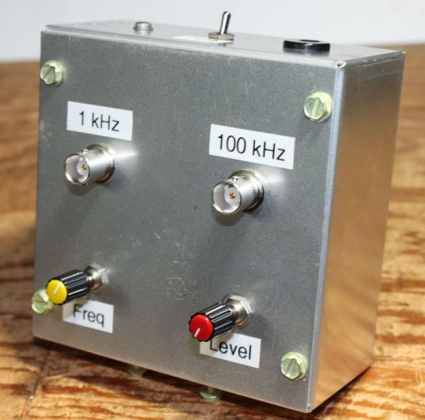
capacitor, and maybe having to repeat the whole thing with an insulated tool. A nice grounded shaft with a knob on it is much more satisfying! You will
note from the picture at the top of this article that the knobs on the prototype are small, and I plan to find something bigger. But you may do as you
please -- a nice 10 or 20 turn trimpot would give a lot of "bandspread" on this adjustment, and certainly would be cheap.
Divider:
Years ago, dividers for an application like this were TTL 7490 decade dividers. Four of them would be necessary to go from 10 MHz to 1 kHz. With microcontrollers,
the job has become easier. U1 is a PIC controller chip, programmed with code shamelessly lifted from: http://wdv.com/Electronics/GPS/ppsdiv/PPSDIV.ASM.
I used this setup a few years ago to provide 0.1 Hz interrupts for the TAG WOLF transmitter. Originally written for the PIC16C84, it provides 100 kHz, 10 kHz, 1 kHz,
100 Hz, and so on, down to 1000 seconds. You are referred to that documentation for explanations of some of the features not used in this project. The 100 kHz
output duty cycle is not a square wave: it has a 20% duty cycle. All of the other outputs are 50:50 true square waves. This has some interesting consequences.
The square wave outputs have very low even-harmonic signal levels. The 100 kHz output does better with even harmonics -- a good thing, as the WWV frequencies are
on even multiples of 100 kHz. I had originally figured that I could use the 10 kHz output for both WWV and CHU (3330 kHz) calibrations. But the levels on 5, 10
and 15 MHz were way too low. If you plan to use CHU for calibration (a very good thing in eastern U.S. and Canada in the daytime), you should bring out the
10 kHz feed. A simple toggle switch could allow a choice of 100 or 10 kHz. The 1 kHz output is also square, and you should try to do your receiver calibrations at
the odd harmonics (more on this later). The waveform is of no concern for sampling rate calibrations. Both outputs are well isolated from the PIC. As built, the
100 kHz harmonic at 10 MHz is -72 dBm with the pot all the way up. The 1 kHz output produces -12 dBm at 1 kHz, -55 dBm at 137 kHz, and -66 dBm at 475 kHz. These
should be sufficient for the intended purposes.
The PIC16C84 code from the original source was altered to allow use with PIC16F84A or PIC16F627A chips. Both are newer, and the 627A is considerably cheaper. This
article includes a Zip file with both the source code and Hex files for both processors.
Pre-programmed chips are available for $7.00 each, which includes shipping within the U.S. Contact John Andrews, W1TAG at [ w1tag@charter.net ]
for more information.
Power Supply:
U2, the 7805 regulator, produces the 5VDC needed for both the oscillator and the divider. At 9VDC input, the current drain is only 8mA, suggesting that the
circuit would run for quite a while with a 9V battery. I would suggest keeping the input voltage below 15VDC, but 24VDC would work with some attention to
heat-sinking the regulator. An unregulated DC wall-wart would work fine. At the moment, I'm using a 12VDC desktop switcher.
Construction:
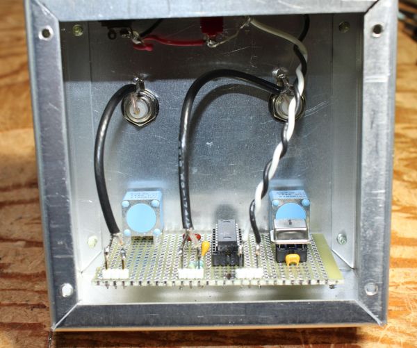
The prototype was built in a 4"x4"x2" aluminum box, which happened to be on-hand. As you can see from the picture above, a piece of perfboard was used, with
the two pots securing the board to the box. The rear of the BNC connectors is shown, and the power regulator circuitry is at the top of the box. There's
nothing critical about most of this. I would suggest sticking with a metal, rather than plastic enclosure, as that 10 MHz signal can be tough to keep out
of a receiver. Standard RF and digital techniques can be followed on the board. There are no present plans to produce printed circuit boards for the
project, but who knows...
Setting the Oscillator Frequency
HF time and frequency stations are the lowest-cost source of calibration signals. As mentioned above, for North America, WWV/WWVH on 5, 10 and 15 MHz are good choices, as is CHU
on 3330 kHz. WWVB on 60 kHz is not a great option for simple beating of two signals, due to the length of time needed for a complete cycle, 167 times longer than
at 10 MHz. That would turn 10 seconds into 28 minutes, and really complicate the process of making small adjustments. The choice of an HF station is governed
by time of day and propagation conditions. You can tell a lot from watching the receiver's S-meter. Besides looking for the strongest signal, you need to
watch the fading pattern. The best conditions are with minimal, and slow fading. The daytime hours are the best, and single-hop propagation would be preferred
over something more complicated. Here in the eastern U.S., 15 MHz frequently has the best daytime WWV signal. But CHU on 3330 kHz, being closer, has very
stable propagation.
Connections: The variable-level 100 kHz output was designed to be simply connected across the receiver input. A "T" connector can be used
to join the antenna, receiver and calibrator. If the HF signal is especially strong, you might want to use an attenuator at the end of the antenna feedline.
A more elegant solution would be to use a hybrid coupler, but as the calibrator is not a 50 Ohm source, the coupler won't be ideally terminated. Either method
should be fine.
Methods: First, consider letting the calibrator run 24/7. You'll hardly be damaging the environment with its 40 milliwatts of power consumption!
Otherwise, turn it on at least a half hour before use. Doing this work at a point when your "shack" temperature is fairly constant would be a help. Those
condemned to working next to the furnace may need to plan a bit. Pick your HF station without the calibrator being connected to the receiver. Remember that
any fading will complicate your job of bringing the oscillator very close to frequency. Connect the calibrator, turn up the output, and set the frequency for a
regular noticeable beat. You may run the receiver in AM, SSB or CW mode. You may find that modes with the BFO on are more useful, as you can really hear the
tone level going up and down. If your receiver's S-meter doesn't work with the BFO on, you will probably need to switch to AM mode to make the really close-in
adjustment. With the calibrator output set for a nice clean beat, try slowing it down until the S-meter is "frozen". The longer it stays steady, the better
job you have done. As noted in the earlier discussion, a beat of 1 cycle every 10 seconds should be sufficient. Having gotten it on frequency, watch it for a
while to see if the oscillator stays put. That will help your confidence if you have a single receiver and need it for other measurements.
Sampling Rate Calibration
With the calibrator set on frequency as described above, you can use any number of methods to determine a computer's actual sampling rate. Start by connecting
the 1 kHz output of the calibrator to your computer's sound card input, in place of the regular receiver connection. The audio output level from the calibrator
should be similar to that from your receiver. If you listen to the tone, it will be a buzzy square wave, but the waveform is not an issue in this application.
Here are some examples of doing sampling rate calibrations with several common programs:
Argo: The following applies to Argo Version 1, Build 143, which was current at the time of writing. Start the program,
set the frequency scale on the right so that 1000 Hz is centered, and select the Mode that you intend to use. In my case, that was
QRSS60, and I suggest that as a starting point. Go to Setup, then select Calibration. Put in "0" for offset in the box on the right. Enter "1000" for the Measured Frequency
and Displayed Frequency. Click OK, and then start the trace by clicking Start. Adjust the level controls to produce a clean, thin
trace near 1000 Hz. It's very unlikely that the displayed frequency will be exactly 1000 Hz. Note the "Peak at" reading at the top
of the screen. In my case, it was 999.85 Hz. Open the Setup/Calibration screen again, and enter that frequency into the "Measured frequency"
box. Click OK, and you should see the main screen "Peak at" reading go to 1000 Hz +/-0.01 Hz. At this point, you have compensated for the
sound card sampling rate. If you try other modes on Argo, you will see some deviations in measured frequency. It can really only be
considered to be "exact" for QRSS30 and slower. But that's the range in which we are most concerned with accurate measurements.
Spectrum Laboratory: The following was done on Spectrum Laboratory 2.79. This is a complex program, and has very
good instructions for calibrating the sampling rate. The follow tips may answer some questions. Click Options, and Audio Settings.
Decide which sampling rate you want to use, and choose from table at Soundcard Sampling Rate. Be sure that the input SR is decimated
by 1, and that the entry in the table below that is the nominal rate you have chosen above. In my case, I used 11025 Hz. Click Apply,
and close that screen out. Now go to Quick Settings, Slow Morse Reception (QRSS), and choose QRSS30. Enter a center frequency of
1000 Hz, click OK, and decline to setup the DigiMode Terminal. Select Options, FFT Setup, and change the FFT Input Size to 262144.
Click Apply and Close. Now go have a cup of coffee, raise a family, whatever it takes to wait out the program. When it starts to run,
use the cursor to display the peak of the measured frequency. Go back to the Audio I/O screen, and use the Samplerate Calculator on
the right to enter the nominal 1000 Hz frequency, and the measured frequency. Click Calibrate Input SR, and the calculated sampling
rate will be applied. Feel free to play with other sampling rates, and have plenty of time available.
WOLF GUI: This applies to the WOLF GUI program by DL4YHF, last updated in 2008. Start the program, and go to the WOLF Config
tab. On the right, enter the nominal sampling rate you wish to use. My particular computer is subject to nastiness at 48 kHz, so I would
normally use 22050 Hz or lower. In this case, I enter 11025 Hz. Enter a Center frequency of 1000 Hz. Click the Special tab, and be sure
that Frequency measuring interval is set to 60 seconds. Now click Main Screen, Mode and Frequency measurement. The program will run,
and every 60 seconds will spit out the frequency deviation from 1000 Hz. Not surprisingly, in my case I got a string of -0.150 readings.
Since 1000 - 0.150 = 999.850 Hz, go back to the Wolf config tab, click CAL, and enter your results. The program will calculate a
sampling rate, which in this case was 11026.654 Hz. Accept that, and your sampling rate is properly calibrated.
Frequency Measurement.
Receiver Offset Calibration
Most receivers don't produce the exact expected audio frequency due to factors mentioned earlier. The 1 kHz markers from the calibrator
allow you to determine the offset, and then you can enter that number into the DSP program to get correct over the air frequency
readings. Just connect the 1 kHz output to the receiver input (disconnect the antenna). If you use CW mode on your receiver, set the
receiver tuning to an ODD multiple of 1 kHz near the frequency range you plan to use. The DSP program should be set to be centered
on the expected BFO pitch from the receiver. I use 800 Hz...others have their preferences. On the other hand, if you use USB mode
on the receiver, set the receiver dial 1 kHz below that odd multiple of 1 kHz. For example, if I wish to calibrate at 137 kHz, set
the USB receiver to 136 kHz to produce a 1 KHz audio output. Then go look for that 1 kHz with your DSP program. Here are some notes
on the three programs discussed above:
Argo: Start Argo, select the QRSS speed, and get the expected frequency in the center of the display on the right.
Click Setup and Calibration, and verify that the Offset is set to zero. Close the Calibration window, and start the program. Once
everything has run for a while, make note of the Peak at frequency at the top of the screen. I got 800.21 Hz instead of 800.0 Hz.
Open the Calibration screen again, and enter the desired offset, in my case -0.21 Hz. Close calibration, and you should see the line
correctly calibrated.
Spectrum Laboratory: With SpecLab set up and running on the frequency you have chosen, use the cursor to determine
the frequency of the tone from the receiver. In my case at 137 kHz, I got 800.21 Hz instead of 800.00. So open Options, Spectrum (2),
and fill in the offset value in the Radio Frequency Offset box. Here, I entered -0.21 Hz. When you click Apply and Close, you should
notice that the line has snapped to the correct value.
WOLF Gui: Start the WOLF GUI program, and select WOLF Config. Enter the expected Center Frequency. In my case, that was
800 Hz. The click Main Screen, Mode and Frequency Measurement. As with the sampling rate, let it run for a few 60 second sampling
periods. In my case, I got 0.211 Hz. Go back to the WOLF Config screen, and enter the actual center frequency, which in my example was
800.211 Hz. Double-check your work by re-doing the Frequency Measurement. You should now get 0.000 Hz.
Other Ideas
If you already have a stable 10 MHz frequency source, such as a GPS-Disciplined oscillator, or just a good oven-controlled crystal oscillator,
you can use the divider chip from this project to provide the 1 kHz calibration signal. A suggestion: Unless you have a nice, fast rise-time
10 MHz signal, run it through some conditioning circuitry before going into the PIC divider. I suggest using the input circuitry from a
74HCT4046A. Feed the signal into pin 14, and take it out on pin 2. Pins 3 and 5 tie to VCC, and 10 and 11 to ground. Makes a clean waveform.
If you are interested in an alternate method of sampling rate calibration with Spectrum Laboratory and VLF signals, check out this article by
Jay Rusgrove, W1VD: http://www.w1vd.com/SoundcardCalibration.html.
If you have any questions or suggestions about this project, please contact John Andrews, W1TAG [ w1tag@charter.net ].
Back to Home