Thoughts on Balanced Transmission Lines for LF Receiving
Basics
Two-wire transmission lines are used to couple antenna or preamplifier outputs over some distance to receivers.
The most common form are coaxial lines, probably because that's what we are used to at HF. These are inherently unbalanced
with respect to ground, as the outer conductor forms one wire, and the inner conductor the other. Loss is typically not an issue,
assuming reasonable impedance matches at both ends. Such lines are inherently self-shielding against electric fields.
In professional audio work, balanced 2-wire lines are normally used to carry signals in the sub-millivolt to volt range.
The concept is that external magnetic field lines would induce the same voltage (with respect to ground) into each conductor, and
the differential voltage between conductors would be very low. With transformer or active-balanced circuitry at both ends of the
line, any common-mode signals can be almost completely rejected. Twisting and close spacing of the two conductors
may enhance the noise rejection, as they help insure that both conductors have equal exposure to unwanted magnetic fields. In the case
where cables carrying strong signals are used in proximity to weak-signal circuits, these techniques reduce coupling between them.
If needed, some protection from strong electric fields can be provided in transformer construction, or in cable shielding
where the shield is not used to carry signal currents.
It is interesting than many LF radio enthusiasts using coaxial cable to connect to receiving antennas wind up putting transformers
or common-mode chokes at one or both ends, to reduce noise. This suggests that further improvement might come from the use
of balanced lines instead of coax.
Types of Balanced Cables
Telephone wiring was for years the most widespread example of balanced audio wiring. With lengths in miles, great pains were taken to
keep the pairs balanced to ground, keeping noise and crosstalk within industry limits.
Professional audio wiring is typically done with two lightly-twisted insulated conductors enclosed within a shield, the shield likely
only grounded at one end. Foil shields are now the rule in indoor situations where the cable is not flexed, as the foil may crack due to
repetitive movement. Microphone cables typically have fine-stranded conductors (with more twisting) and braided shields, adding to durability.
The latter cables can be expensive - more than a dollar per foot. They have definite possibilities for LF transmission lines,
but may be overkill, given other alternatives.
Ethernet cables, Category 5 or greater, offer four highly-twisted pairs, either unshielded or with a foil shield. With tightly-controlled
construction and installation, these cables are expected to carry fast rise-time signals at rates of tens of Megahertz. Such wiring is
very appropriate for our purposes, and will be explored below.
Ethernet Cables
While just about any Category 5+ cable may be used in an interior application, you will definitely want to consider outoor or plenum
cable for outdoor installations. These cables have a much thicker jacket, and will last for years when exposed to the weather. Experience
with indoor-type cables outside has not been good except for short experiments. Outdoor installations might benefit from stranded cable if there
is to be much flexing. All of my experiments to date have been with unshielded cables. Since foil shields are the norm, any benefits in
outdoor installations might not last. Otherwise, there doesn't seem to be any advantage to paying premium prices in these applications.
The four pairs in an Ethernet cable may be grouped as:
White-Blue/Blue-White
White-Orange/Orange-White
White-Green/Green-White
White-Brown/Brown-White
Each pair is equivalent for our use, allowing you to use any of them interchangeably.
Category 5+ cables have a nominal characteristic impedance of 100 Ohms for each pair. For those of us who wish to maintain 50 Ohm RF
systems, that suggests putting two pairs in parallel as a transmission line, leaving the other two pairs available for power or control
purposes. You must remember, of course, that these wires are in very close proximity, and some conditioning of power/control circuits will
be necessary to maintain a good signal to noise ratio on the signal pairs. While any cable terminations may be used, it is convenient to use
the typical crimped 8-conductor modular plugs pinned out with the colors in standard Ethernet fashion. The only catch is that such plugs are
not very weather-tolerant, and you'll need to locate the jacks in weather-protected environment. While cable-routing can be important for
authentic high-speed Ethernet purposes, a little common-sense will probably keep you out of trouble at LF.
I have been using the first two pairs for the signal, connecting the White-Blue to White-Orange, and the Blue-White to the Orange-White at
both ends of the cable. This parallels the two pairs for use in a 50 Ohm system. In the simple case where no preamp is used at the antenna,
the other two pairs may just be left floating. If preamp power is needed, you can parallel the remaining pairs for lower voltage drop,
and feed the power through them. Recommendations are given below for conditioning the power connections at both ends, to avoid coupling
noise into the nearby signal pair.
RF Coupling Methods
Transformers are strongly recommended for coupling at each end. Typically, you will need to make 1:1 transformers in an effort to preserve
the 50 Ohm system. For the frequency range under consideration (up to 500 kHz), there is no need to adopt transmission-line transformer
construction. Separate primary and secondary windings should work well, and offer the best balance. Toroidal cores are easy to work with,
and offer minimum coupling to other circuitry, as the magnetic fields are mostly confined in the core. High-permability ferrites such as
77 material are appropriate. The goal is to have the reactance of each winding be at least five times the impedance to be matched. That
would mean +j250 Ohms for a 50 Ohm system. The core and wire size should be big enough to use 80-90% of the core for each winding.
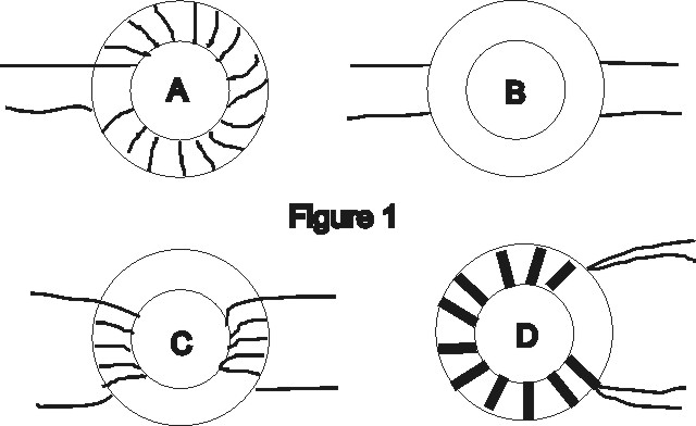
Referring to "A" in Figure 1 below, one winding can be wound with enamel wire directly on the core (some may prefer to lay down a layer of
fiberglas tape first). Then cover the winding with a layer of fiberglas tape (Scotch 27 - you may need to cut it into lengthwise strips for
small cores). Then lay down the second winding over the first, with the start/finish wires leaving the other side of the core as in "B". Avoid
the type of winding in "C," where the primary and secondary are separated. This leads to uneeded leakage reactance in the transferred impedance.
Also, avoid winding methods that provide too much capacitive coupling between the windings, such as the bifilar method in "D". An ideal
approach would be to provide a Faraday shield between the windings, but that isn't a simple task with a small toroid core. Any such shield
cannot form a complete turn, or the inductance will be be lost. This could be done with a very thin strip of copper or brass which forms a "C"
shape around the core. It could also be done with an isolated winding of fine insulated wire between the primary and secondary, with one
end of the wire grounded, and the other floating. To date, I have not tried this, as the balance of the unshielded transformer appears to be
sufficient.
A good test of success is to leave the far end of the cable floating, and connect it through the transformer to a receiver. If the
balance is good, there should be very little signal or noise pickup, as there is no differential signal across the line.
Decoupling of Non-RF Conductors
There's a temptation to use the other two pairs for some purpose, and we will focus on providing power from the shack to a preamp or
similar load at the antenna end. The trick is to provide the cleanest power possible, both for the happiness of the preamp and to prevent
noise coupling in the long run of wires in close proximity.
Batteries are very clean power sources, and provide a good comparison for the AC supply you will probably wind up using.
Batteries are great, but a little impractical for 24/7 monitoring. If you do use a
battery, a lot of conditioning is not necessary. I would certainly recommend a good common-mode filter at the preamp end, if a real earth
ground is used in the antenna circuit. That will insure that the power pairs are decently balanced to ground.
For AC power, you need to start with a nice, clean supply. That pretty much rules out switchers, unless heroic measures are taken.
You might want to follow some of the recommendations in the
AMRAD active LF antenna article from September, 2001 QST. By minimizing the coupling to noise from the AC line, you can save a
lot of choking and filtering later. A bigger issue may be coupling noise in from any earth ground connections you make. The AMRAD power supply
design ducks this by not carrying through a ground from the AC line or case. While this might be an issue for meeting compliance testing
requirements in a commercially-designed product, it's a pretty good idea in our application. It also helps break up the inevitable ground
loop if the antenna works against ground at the far end.
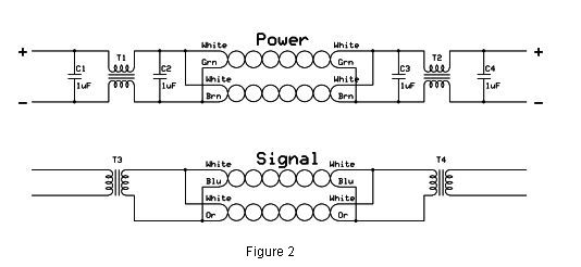
Referring to the power section of Figure 2 below, note that we are doubling up on the pairs to reduce voltage drop. There are two common-mode
transformers, T1 and T2. I have been using the AC-line common mode transformers from discarded switching supplies with good success. You
can't skimp on inductance for LF receiving purposes. Each winding in the transformers I have been using is "worth" 20 mH. That provides decent
decoupling at LF and MF, but would probably be skimpy for VLF. Unfortunately, these second-hand parts are not available from their Chinese
suppliers (at least in quantities without a lot of zeros at the end). Corcom and others do provide alternatives available from traditional
suppliers. Look for inductance values in the 20 - 100 mH range. Regarding the rest of the power circuitry, do NO bypassing to ground
on the line side (i.e., associated with C2 or C3). Unless capacitors can be accurately matched, they will only degrade the balance. Feel free
to play with large/small capacitors and RF chokes on the C1/C4 sides, however.
Installations
A little common sense goes a long way. Try to avoid parallel runs with AC lines, or cabling carrying fast rise-time
signals. I have had good luck just laying the cable on the ground, with slack provided for mowing. You could consider creating
an extra common-mode choke by winding some of the cable around a large (say, 2.4") toroid, but it's tough to create much real
inductance that way. It probably would make a decent lightning choke, however! Most of the typical recommendations for grounding
and choking only apply to coaxial cables.
As a special case, consider an active whip antenna mounted at some height above ground. You have two possibilities. One is to run a ground
wire from the preamp to a ground underneath the antenna. You can simply run the balanced feedline parallel to that, or at any needed angle. The
second would be to use a metal pipe to support the antenna. Ground the pipe at the bottom, and be sure it contacts the preamp case at the top.
Then run the feedline inside the pipe. Realize that in both cases, the ground connection is not only essential to operation of the antenna,
it is most of the antenna itself. The pipe approach is highly recommended.
A more unusual situation has been with a receiving antenna at my site in Maine. The antenna is a 500' wire lying directly on the ground
in the woods. The wire ends at a ground stake, and I have used both a high input impedance preamp and a 70:12 turn coupling transformer
to connect it to the Cat 5 cable back to the shack. The present arrangement uses the transformer only, leaving the other two pairs in the cable
unconnected. A 50 ohm, 20 dB preamp in the shack is used ahead of the receiver. That has turned out to be quieter than having a preamp
at the end of the antenna, even using battery power.
Back to Home