518 kHz Elliptical 50 Ohm Low-Pass Filter
Many of us who do weak-signal receiving work in the 500 kHz and below world are plagued by intermodulation products from
nearby AM radio stations in the 530-1710 kHz band. The most common spurious responses are simple mixing products, the difference
between two strong AM signals. The filter described in this article has a very steep attenuation curve, with a -6 dB breakpoint
of 518 kHz. It was designed for use in a 50 Ohm system, for reception at 510 kHz and below. The filter is only useful for
protecting the equipment that follows it; if the mixing occurs in a preceding antenna or preamp, the damage can't be undone. Also,
mixing products may be created in nearby poor metallic connections, and filtering won't help.
The author is blessed with a 5kW AM directional station on 580 kHz, about 2 miles away. That results in a 650 mV/m signal at my QTH
in the daytime, and 400 mV/m at night. Other nearby stations are on 830, 1230, 1310 and 1440 kHz. My Icom R75 receivers are
definitely capable of producing spurs from these signals, and this filter has been a big help in reducing them.
There are a number of filter types that could work in this application. Jay Rusgrove, W1VD has a nice tuneable bandpass filter article
on his website: http://www.w1vd.com/500khzpreselector.html. This filter is
for use in the 500 kHz region, and can be scaled to cover the 472 kHz band. My approach was to use a low-pass filter, but I needed
a sharp cutoff at the lower end of the AM band, due to the 580 kHz station. This rules out filters such as Butterworth, Gaussian,
Transitional, and even Chebyschev. The most suitable topology is the Elliptical, and a good-sized one, at that. I used information
and design tables in "Electronic Filter Design Handbook" (3rd Edition) by Arthur B. Williams and Fred J. Taylor. From the curves
presented in the book, a 9th order response appeared to be necessary to provide the steep attenuation curve. After an initial run, it
seemed possible to place a zero in the response close to 580 kHz, so I went through a number of iterations to choose the proper -6dB point.
I wanted a minimum attenuation of 60 dB in the 580 kHz region, and not too much ripple in the filter passband from DC to 510 kHz or so.
For the 9th order filter, this translated to a passband ripple of 0.18 dB (20%), a breakpoint of 1.1126 times 518.047 kHz, a steepness angle
of 64 degrees, and a minimum attenuation of 63.5 dB. The table on page 11.98 of the book gave the normalized values for all of the elements in
the filter, as well as the parallel resonant frequencies of the four sections.
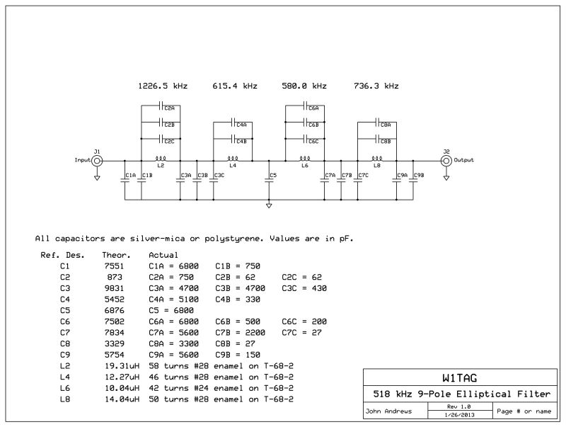 The table below the schematic gives the theoretical value for each part. For the capacitors, note that I generally had to use two or three
capacitors in parallel to come close to the desired value. I did some measurements to be sure that each part was within 2% of its stated
value. Be assured that some of the choices are very arbitrary, just making use of parts on hand. You would be free to choose parts from
your own collection! Silver mica or polystyrene capacitors are preferred. It's getting tough to find such parts in through-hole
configuration, so if you are buying, be sure to check out the surplus market. The inductors were all wound on Amidon T-68-2 toroid
cores, which yield high-Q coils in this frequency range. I didn't obsess about hitting exact inductance values once I saw how closely
the finished filter matched expectations. Here's the measured response of the filter as built:
The table below the schematic gives the theoretical value for each part. For the capacitors, note that I generally had to use two or three
capacitors in parallel to come close to the desired value. I did some measurements to be sure that each part was within 2% of its stated
value. Be assured that some of the choices are very arbitrary, just making use of parts on hand. You would be free to choose parts from
your own collection! Silver mica or polystyrene capacitors are preferred. It's getting tough to find such parts in through-hole
configuration, so if you are buying, be sure to check out the surplus market. The inductors were all wound on Amidon T-68-2 toroid
cores, which yield high-Q coils in this frequency range. I didn't obsess about hitting exact inductance values once I saw how closely
the finished filter matched expectations. Here's the measured response of the filter as built:
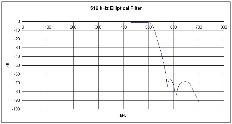 The design goals of -6dB at 518 kHz and -67.5dB at 580 kHz were met. Insertion loss was under 2dB from DC to 506 kHz.
Here's a picture of the interior of the finished filter:
The design goals of -6dB at 518 kHz and -67.5dB at 580 kHz were met. Insertion loss was under 2dB from DC to 506 kHz.
Here's a picture of the interior of the finished filter:
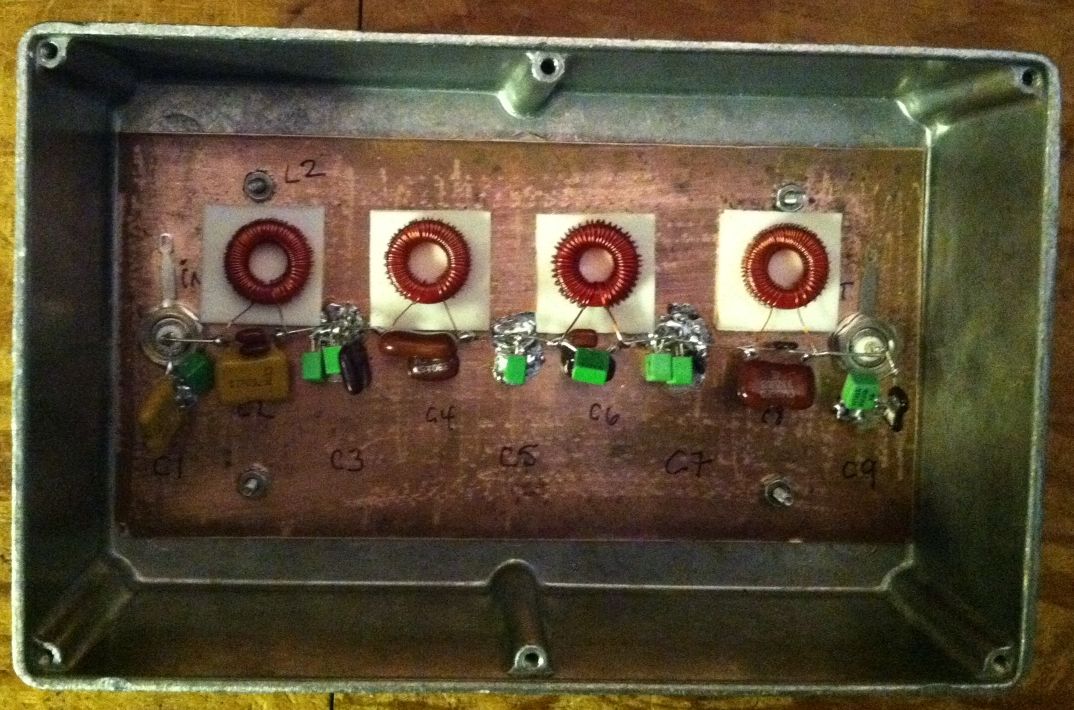 The filter is built on a piece of unetched circuit board, with the copper forming the ground plane. The inductors are mounted
with 3/4" foam adhesive pads, which spaces them up a bit from the copper, reducing the stray capacitance. The size of the coils
pretty much determines the dimensions of the filter, though it could certainly be tightened up.
The filter is built on a piece of unetched circuit board, with the copper forming the ground plane. The inductors are mounted
with 3/4" foam adhesive pads, which spaces them up a bit from the copper, reducing the stray capacitance. The size of the coils
pretty much determines the dimensions of the filter, though it could certainly be tightened up.
Performance of the filter has been excellent, with virtually all of the mixing products eliminated. The receiver is now
very "deaf" in the broadcast band, even when tuning in the local stations. Of course, care still has to be taken with any
active circuitry placed ahead of the filter. This QTH has been pretty unfriendly to untuned whips, for example, even with the
most "cast-iron" of preamps.
Back to Home