2-Tone Audio Tests for AM Transmitters
Single sine-wave audio tones are frequently used for testing AM transmitters. They are useful for measuring modulation level,
frequency response, THD, and so forth. One frequently needed test involves determining the positive peak capablility of a
transmitter. With a single tone, positive modulation peaks >100% are accompanied by by the cut-off carrier associated with
attempting to modulate >100% in the negative direction. Transmitters, such as those using linear amplifiers, can have a
number of adjustments involving headroom. A steady test signal not driving the rig into distortion can be useful to
maximize the positive peak capability.
A 2-tone audio signal may be used to generate an asymmetrical waveform with positive peaks greatly in excess of negatives,
allowing the negative modulation to stay under 100%. One very useful waveform is generated with equal levels of a single tone
and its second harmonic. The waveform resulting from a signal of cos(2*pi*f*t) + cos(4*pi*f*t) may be graphed by the function
y = cos(x) + cos(2x). A plot of that waveform is shown below in Figure 1.
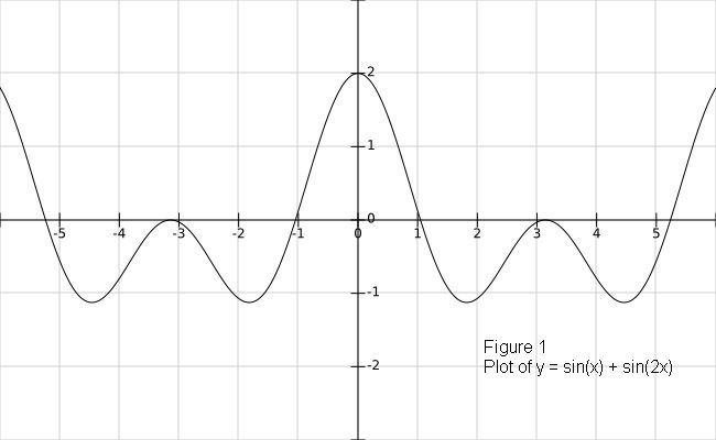
As plotted, this function has y-values from -1.12 to +2.0. Unfortunately, the real audio signal cannot be generated by two
separate audio oscillators, as the frequency and phase must be matched. The (really) good news is that free solutions exist,
assuming that you have an available computer with "sound card" output. My favorite thus far is a 2-tone generator program
TCube written by Alberto DiBene, I2PHD. Just download the installation file
and run it. It will place a "TCube" icon on your desktop. The program screen can be set up to look like Figure 2.
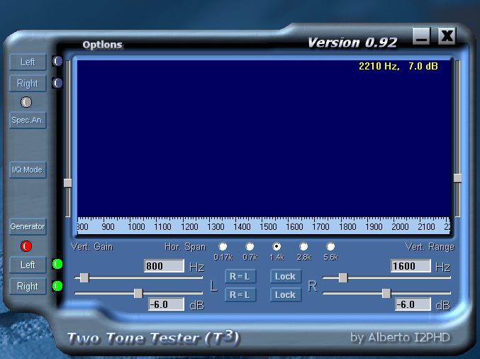
In this instance, I have set the left channel frequency to 800 Hz, the right channel to 1600 Hz, and both output levels to
-6dB. The generator is turned on, and both left and right channels are activated. This should result in an 800 Hz tone on the
tip connection of the computer's audio output jack, and 1600 Hz on the ring connection. The next step is to sum the two signals
together and apply them to the AM transmitter audio input. This could be done with a couple of resistors joined together at the
transmitter end. You could also use an audio mixer by bringing in those stereo inputs and creating a mono mix for the
transmitter. I decided to make up a simple pad/transformer box that sums the two signals, and brings them out at balanced
microphone level. See Figure 3.
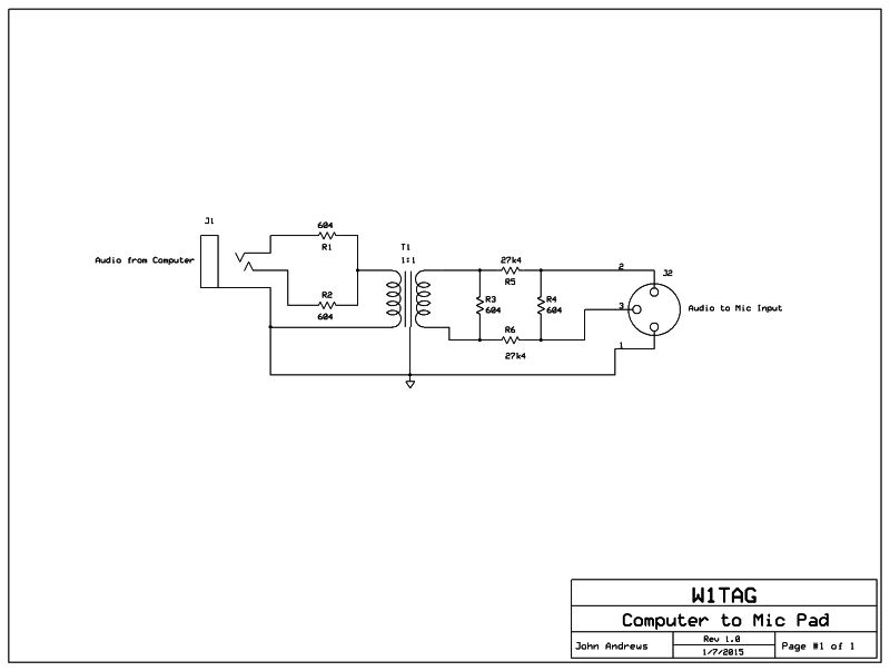
R1 and R2 sum the two channels, and the signal is fed to a good-quality 1:1 audio transformer. I used an available
Sescom transformer, but in the middle of the audio voice range, pretty much anything will work. Note that the transformer
is placed before the pad, which reduces the need for magnetic shielding. If you want to use this for frequency response and
THD measurements below 100 Hz, pick a good transformer. A 45dB 600 ohm pad is used between the transformer and the XLR jack.
Since normal microphone preamps have a higher impedance input, the pad will not be terminated, but no big deal.
A screen shot of the modulation monitor pretty much shows the results on a decent transmitter. See Figure 4 below.
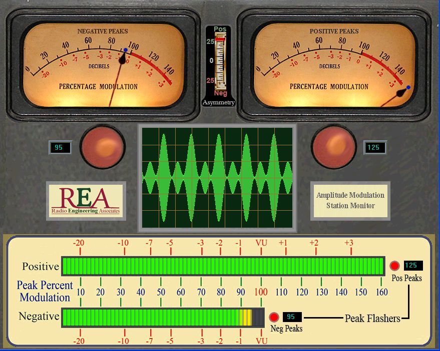
In this case, the rig was a 75 watt class-D rig on 40 meters, modulated with a commercial audio power amplifier. The positive
peaks were clearly >160%, with the negatives at 95%. An oscilloscope can be used to determine the actual positive peak
level.
Other tone combinations may be used to evaluate distortion products, particularly IMD. This method may give you a starting
place.
Back to Home